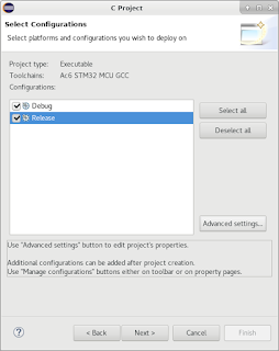
Recently I've decided to venture into an exciting world of homebrewing. Brewing your own beer mostly involves 2 types of manipulations with liquids, namely heating and cooling. While heating can be comparatively easily done with butane burner or electric heater, cooling is a slightly more complicated matter. There are several ways one can go about cooling his/her wort:
Since I was always fascinated with new technology, soon enough a thought came to my mind that Peltier elements are begging to be used in this scenario of cooling a limited volumes of liquid. That's how I decided to try making something like an immersion chiller with finite reserve of water cooled by Peltier modules.
This article is meant for those poor souls who, like myself, don't even have access to a steady source of water on their brew day.
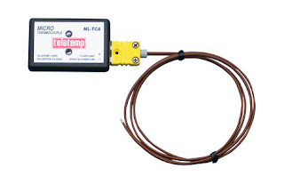
I started my experiments by buying
![]()
From all this stuff we can fashion a sort of heat exchanging sandwich. It'll look like that:
![]()
Obviously cold side of TEC element goes to the heat exchanger, while the hot side goes to CPU heatsink with fan.
Now, I wonder if this will even work... And if it does, how much current will this 1-sandwich setup suck? Let's try a basic arrangement where the pump gets water from the bucket, pumps it through our heat exchanger and back into the same bucket. Hose will be connected like this:
![]()
![]()
Now, this calls for a small investigation. I'm going to do some benchmark tests to determine if cooling water via Peltier modules is viable and how much power and TEC modules is required to cool wort in volumes and time frames that brewing requires (around 30L from 100°C to 25°C in no more that 40-50 minutes).
Since 1-sandwich setup was nigh useless, I started benchmarking with 2-sandwich setup:
![]() I'll be posting results here as I get them:
I'll be posting results here as I get them:
 Recently I've decided to venture into an exciting world of homebrewing. Brewing your own beer mostly involves 2 types of manipulations with liquids, namely heating and cooling. While heating can be comparatively easily done with butane burner or electric heater, cooling is a slightly more complicated matter. There are several ways one can go about cooling his/her wort:
- Ice bath. As primitive as dropping your vat of wort in a sink or tub filled with mixture of ice and water. Impractical for bigger volumes and brew pots that you can't even lift. May be a great way to exercise for a rare combination of DIY brewer and weightlifter.
![]()
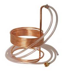
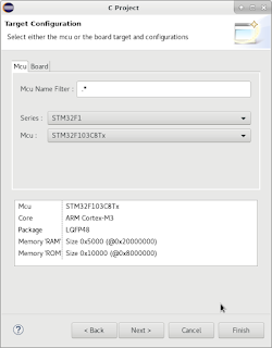
Ice bath - Immersion chiller. A coil of copper through which cold mains water flows. You submerge it in your brew tank and magic happens.
![]()
Immersion chiller - Counterflow chiller. This one is similar to the previous variety except it's built as a coil within coil. Now you don't have to sterilize your copper coil and submerge it in wort. Inner coil is for hot wort that is recirculated until it's cool enough, outer coil is fed with mains water supply.
![]()
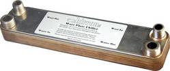
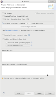
Counterflow chiller - Plate chiller. Basically it's a compact version of counterflow chiller where heat exchange takes place in plates instead of coils.
![]()
Plate chiller


Since I was always fascinated with new technology, soon enough a thought came to my mind that Peltier elements are begging to be used in this scenario of cooling a limited volumes of liquid. That's how I decided to try making something like an immersion chiller with finite reserve of water cooled by Peltier modules.
This article is meant for those poor souls who, like myself, don't even have access to a steady source of water on their brew day.
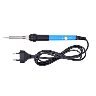
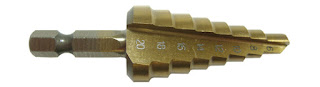
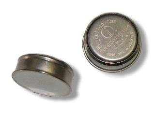
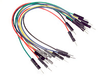
I started my experiments by buying
- 2 40x40mm TEC modules
![]()
- 1 aluminum heat exchanger
![]()
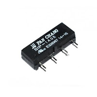
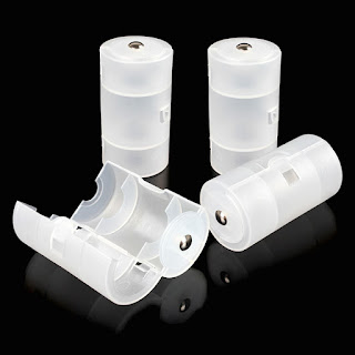
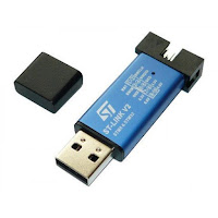
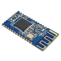
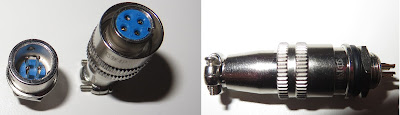
- 1 12v diaphragm pump
![]()
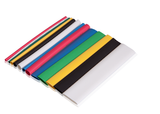
- Flexible tubing ID 6m for pump
- Flexible tubing ID 8m for heat exchangers
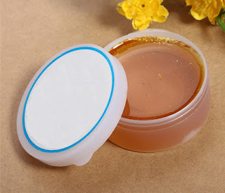
- Thermal paste (considering that heatsinks and peltier modules don't have any mounting holes, you'd be better off with thermal glue)
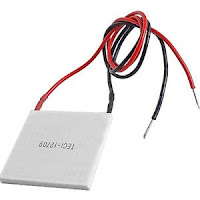


From all this stuff we can fashion a sort of heat exchanging sandwich. It'll look like that:

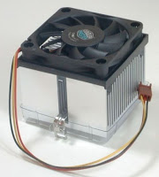
Obviously cold side of TEC element goes to the heat exchanger, while the hot side goes to CPU heatsink with fan.
Now, I wonder if this will even work... And if it does, how much current will this 1-sandwich setup suck? Let's try a basic arrangement where the pump gets water from the bucket, pumps it through our heat exchanger and back into the same bucket. Hose will be connected like this:

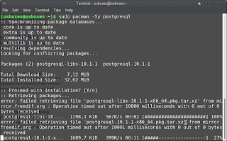
And there's the whole setup:

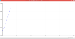
Hook it up to 12V (I recommend computer power supply. You can even make a bench PSU out of it, see my article) and if your wires haven't started smoking (1 TEC pulls about 5A, 2 of them - 10A) you will see water actually cooling down! The speed at which it'll cool is awful though. After 10 minutes of cooling the temperature of 1/10th of a bucket dropped only 2°C:
|
|


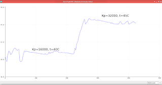
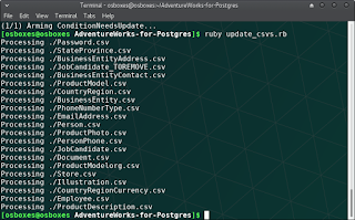
Since 1-sandwich setup was nigh useless, I started benchmarking with 2-sandwich setup:

| # Modules | Total current | Total power | Water volume | Start temp °C | Final temp °C | Temp diff | Time |
|---|---|---|---|---|---|---|---|


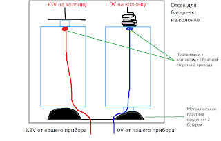
 Сегодня я покажу, как перевести старую, жрущую батарейки газовую колонку на автономное питание (то есть будет работать вне зависимости от того, есть электричество или нет) которое не требует постоянной смены батареек.


 See
See 


 Часть 1
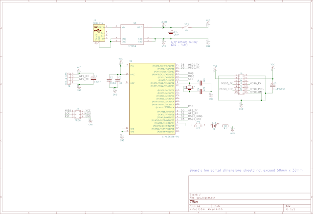


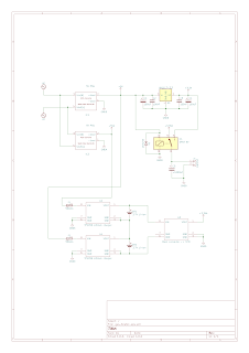
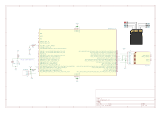
 The idea of the device I'm about to share with you (this may lead you to believe that I'm only going to share an idea, but I'm a tinkerer, not motivational speaker - scroll down for schematics and sources!) was born out of events completely irrelevant to microcontrollers or any technology whatsoever.


 Привет! Эта статья - приложение к видео на моем канале: